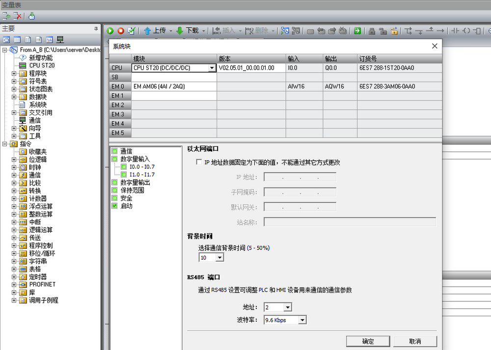
打开PLC组态软件STEP 7-Micro/WIN SMART, 对PLC进行组态。
![](http://doc.cntworld.cn:8080/wp-content/uploads/2024/02/1-59.png)
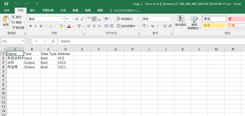
建立输入输出表,是从Factory IO导出的Tag标签文件。
![](http://doc.cntworld.cn:8080/wp-content/uploads/2024/02/1-62.png)
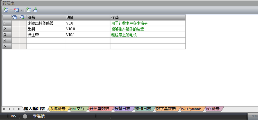
此时的V0.0是代替真实设备的I点,V10.0开头的代替输出Q点。
![](http://doc.cntworld.cn:8080/wp-content/uploads/2024/02/1-61.png)
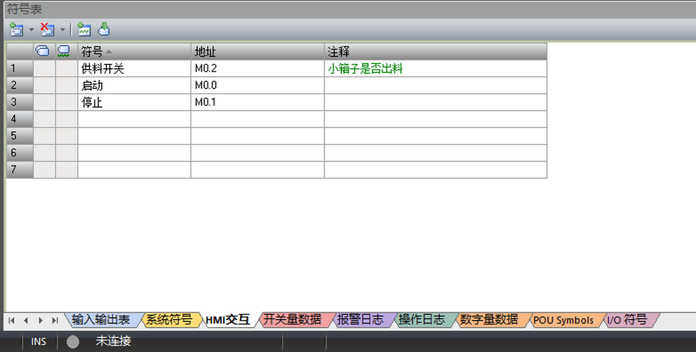
建立的HMI交互符号表,是HMI触摸屏使用的点。
![](http://doc.cntworld.cn:8080/wp-content/uploads/2024/02/1-63.png)
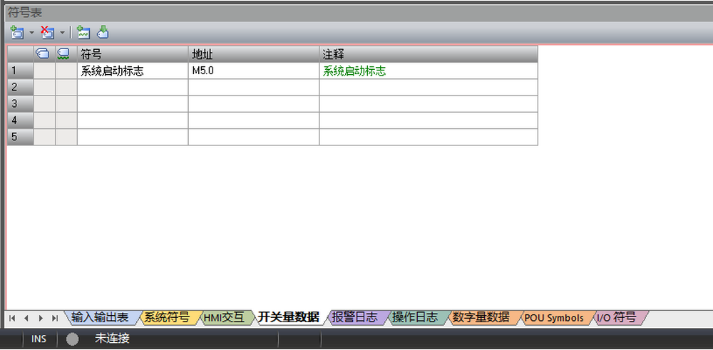
建立的开关量数符号表是用于临时的替死鬼而已,是一些标志位。
![](http://doc.cntworld.cn:8080/wp-content/uploads/2024/02/1-64.png)
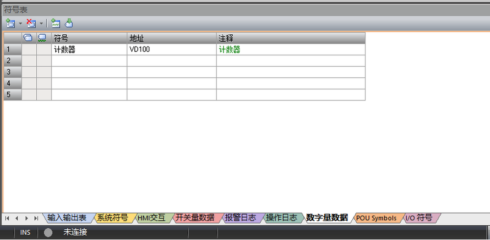
建立的数字量数据符号表是VD数据如,计数器,系统状态,自动状态等数据。
![](http://doc.cntworld.cn:8080/wp-content/uploads/2024/02/1-65.png)
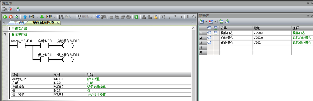
建立的操作日志符号表是一些报警日志,操作日志等,是以VD块出现的,是以组存在的,在触摸屏中一个组是32位,如本例中的VD300, 就可以有v300.0~v303.7个位可以操作。
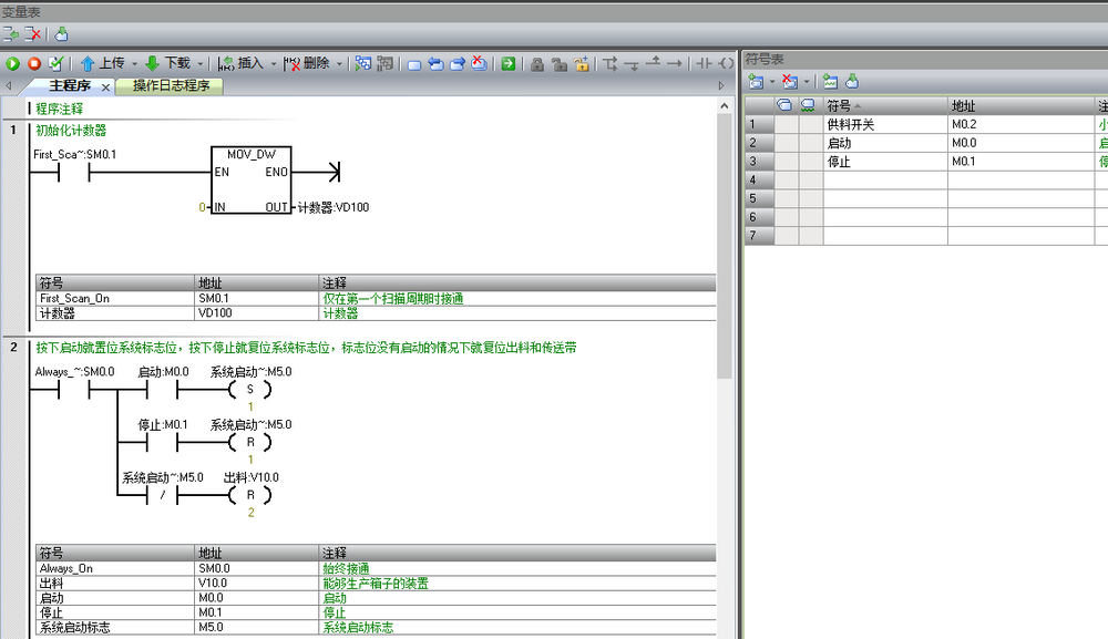
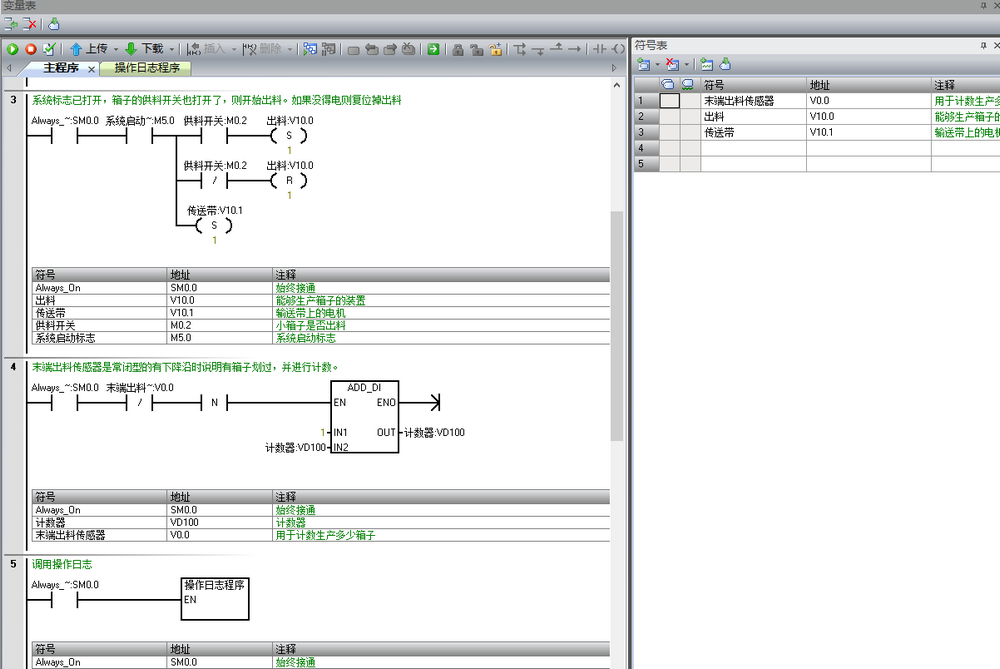
![](http://doc.cntworld.cn:8080/wp-content/uploads/2024/02/1-66.png)
主程序的编写
![](http://doc.cntworld.cn:8080/wp-content/uploads/2024/02/1-67.png)
![](http://doc.cntworld.cn:8080/wp-content/uploads/2024/02/1-68.png)
![](http://doc.cntworld.cn:8080/wp-content/uploads/2024/02/1-69.png)