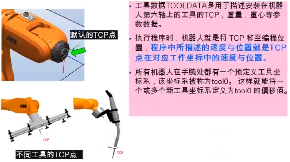
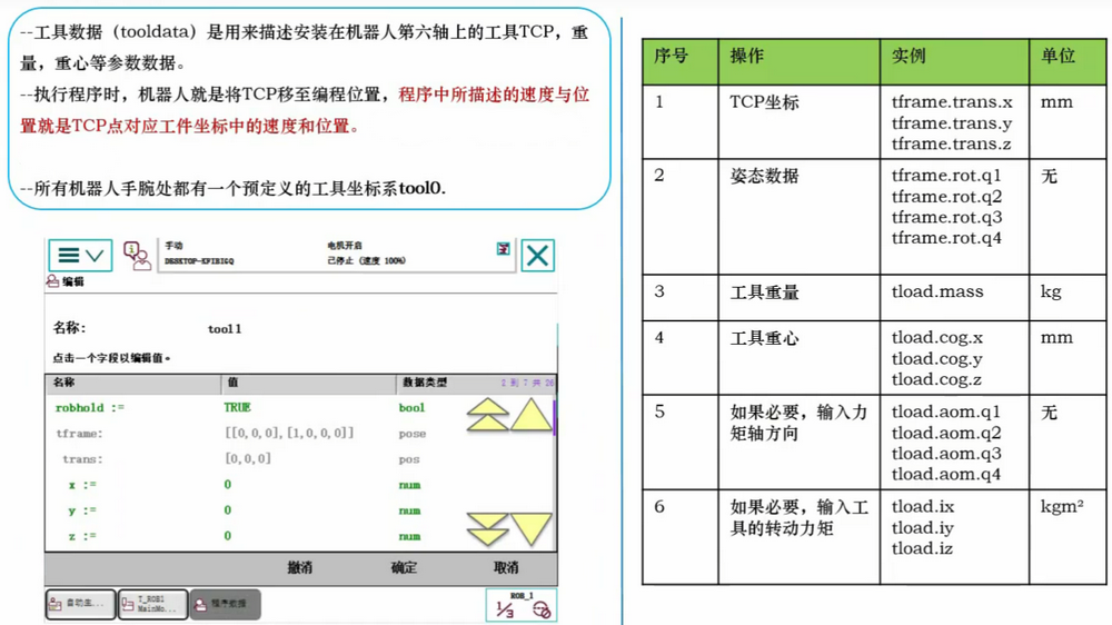
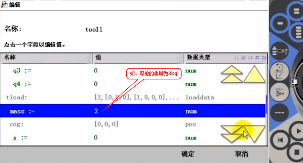
工具数据的原理与设定,工具数据是用于描述安装在机器人第六轴上的工具的TCP,重量,重心等参数数据。
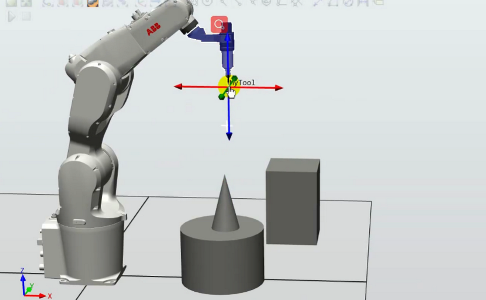
默认TCP的工具数据就是tool0; 垂直于法兰盘向外是Z蓝色;X方向红色;Y方向绿色;都可以用右手法则,母指Z,拾指X,中指Y。
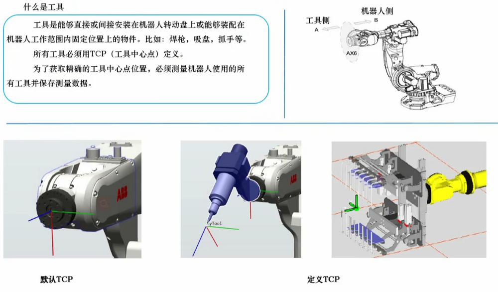
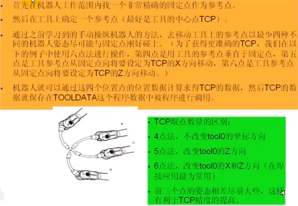
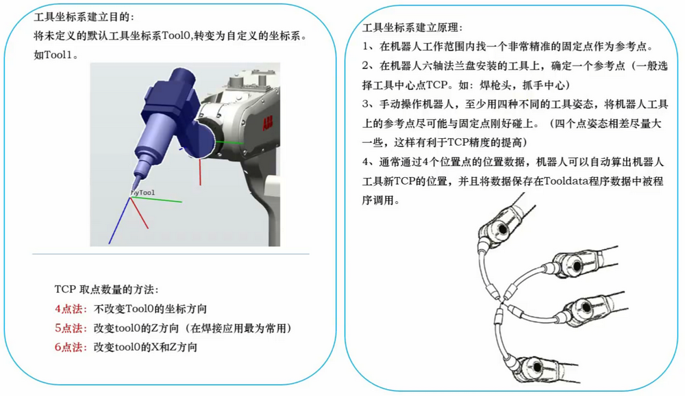
TCP【工具中心点】设定原理
工具数据的定义Tool1
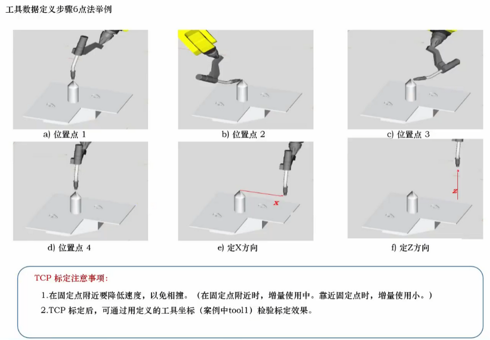
工具数据定义步骤以6点法为例
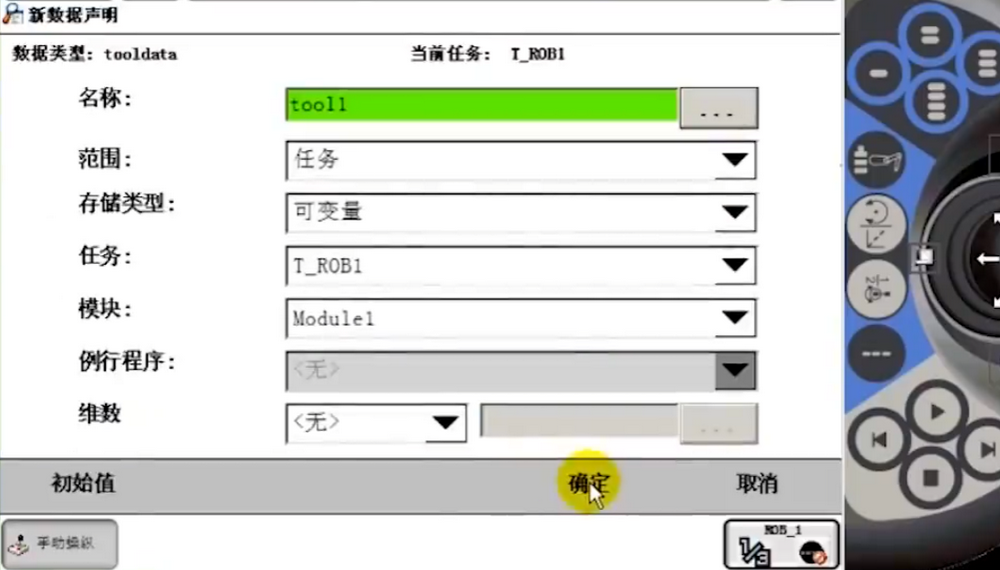
创建一个工具数据tooldata,手动操纵—-工具坐标—-新建—-初始值。
这个工具从法兰盘到焊枪重心的偏移值。工具相对于法兰盘tool0上的重心偏移值。
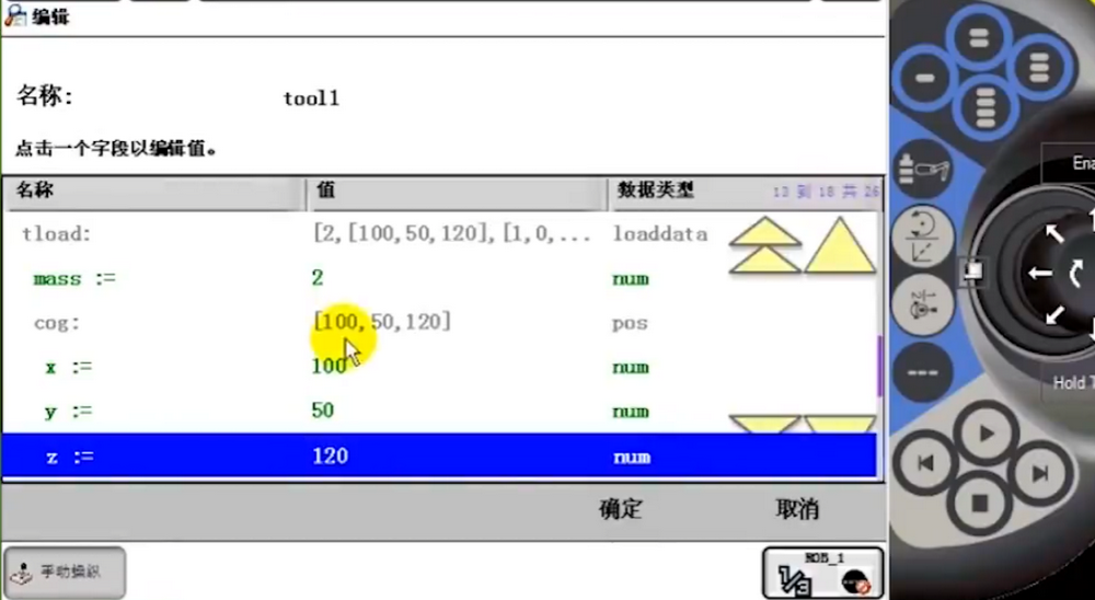
初始值都设完以后点确定即可。
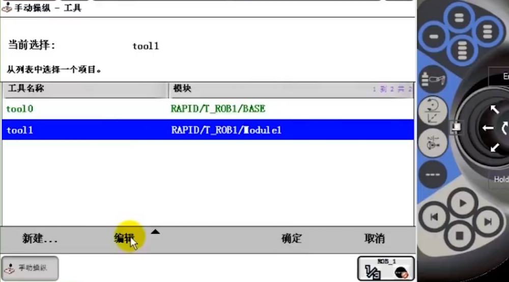
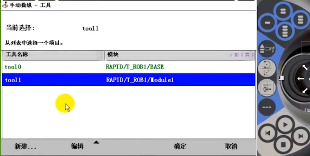
此时就有tool1工具了,选中并点编辑中的定义。
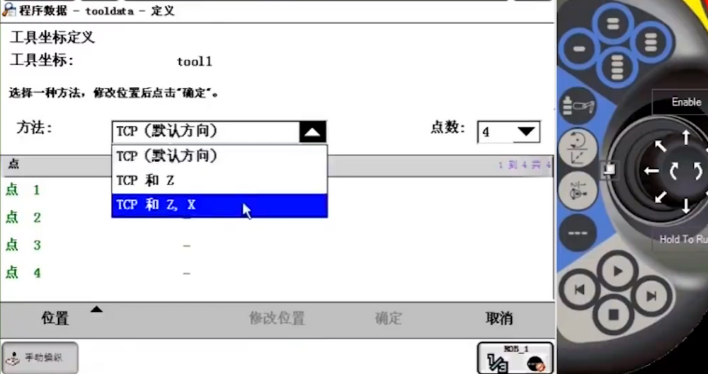
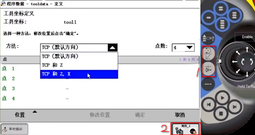
方法:选择TCP和Z,X
此时数据的修改就只能通过框1或框2切换轴来操作了。
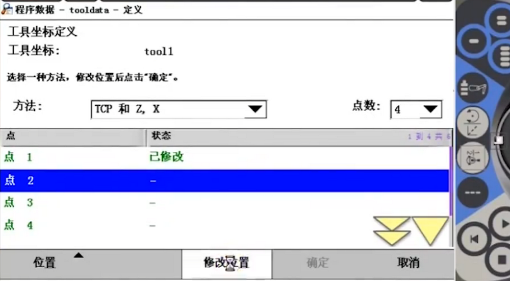
点1,当机器人调整到点1处,选择点1再点击修改位置。

点2,当机器人调整到点2处,选择点2再点击修改位置。

改变姿态,可以通过改变4,5,6轴,就很容易得到偏差较大的点。
点3,当机器人调整到点3处,选择点3再点击修改位置。

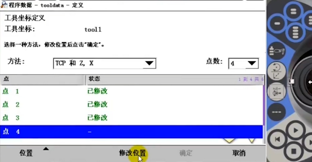
点4,当机器人调整到点4处,选择点4再点击修改位置。

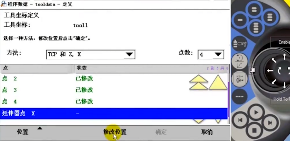
点X,当机器人调整到点X处,选择点X再点击修改位置。

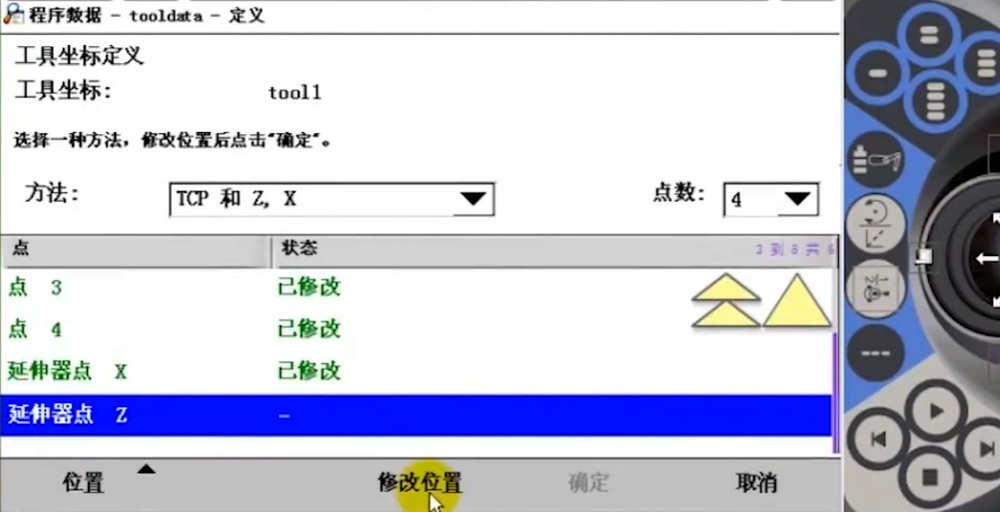
点Z,当机器人调整到点Z处,选择点Z再点击修改位置。

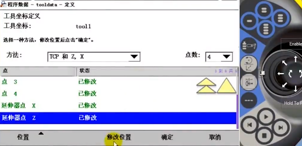
位置都修改完以后点击确定就得到了tool1的工具坐标了。
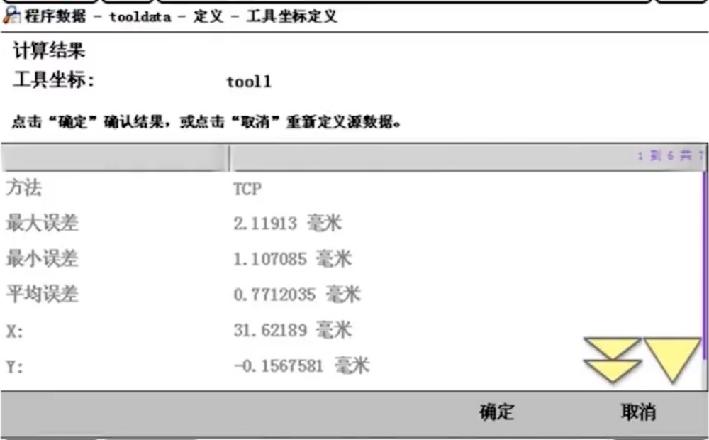
选择新建的tool1工具数据来验证是否准确。点击确定
通过不停的改变姿态,而焊枪头是不会发生偏移的,说明工具数据参数点找的就比较好。

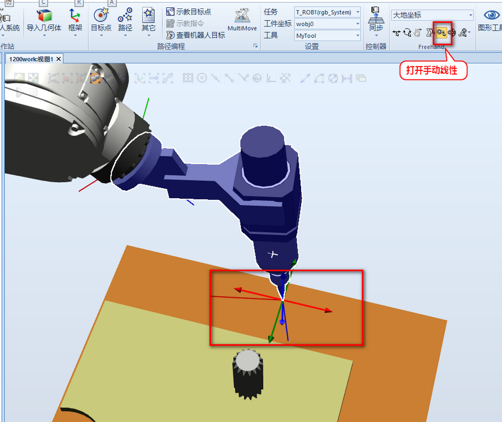
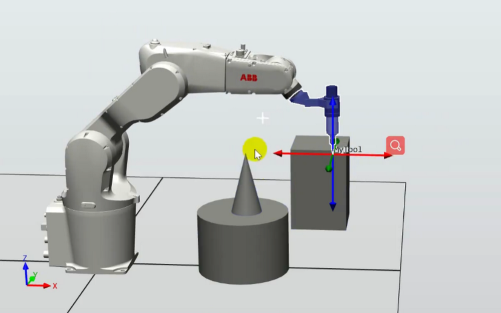
用RobotStudio软件来创建tool1 工具数据。打开手动线性进行拖拽进行对齐。
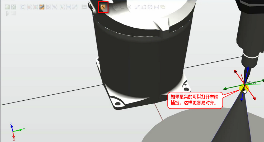
如果是尖的可以打开末端捕捉,这样更容易对齐。
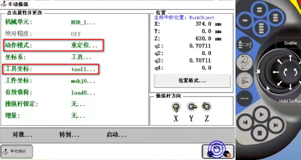
用线性的方式是很不好对齐的,可以切换到重定位的方式。

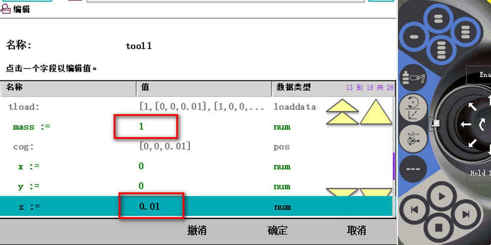
需要修改工具的重量,和重心。否则会报警
X点的延伸点
Z点的延伸点